

You may be able to write the most eloquent code in the history of embedded systems but without a way to run it on the hardware it will be worthless. In this installment of the tutorial series we will:
- Look at some of the available AVR programmer options
- Place the microcontroller on a breadboard and connect it to a power supply and a programmer.
- Use programming software to send some example code to the microcontroller
If you missed Part 1 take a few minutes to review that portion of the tutorial and then join us after the break.
Programmers
As I said before, if you want to get it on the chip you’ve got to have a programmer. There are a huge number of options, but I’ll cover a few of the easiest and least expensive. We are focusing on In-System Programming (ISP) which means that you can program the chip without removing it from the circuit.
DAPA Cable
A Direct AVR Parallel Access, or DAPA cable, is an incredibly simple and cheap programming method. You can build one very quickly for a few bucks worth of parts, but the convenience comes with a few gotchas. The first is that you must have a parallel port on your computer; something that modern laptop and some modern desktops don’t have. But if you’ve got an old PC around that has one this will get you up and programming in no time.
In fact, the first AVR prototyping I did was with one of these cables. That is, until I discovered another gotcha. This will only program low-speed chips. If you try to run the chip’s clock at full speed (by changing fuse settings… more in Part 3) you won’t be able to use a DAPA cable to talk to it any longer. There’s also the*possibility*of damaging your parallel port or worse if you do something wrong. But if you want to go for it anyway, here’s how I built mine.
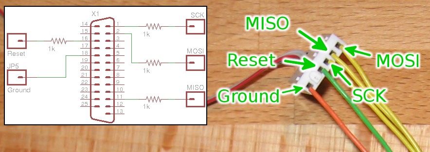
It connects to a computer using a DB25 connector. As you can see in the schematic, I’ve used 1 kilo Ohm resistors on the Reset, SCK, MISO, and MOSI pins for current protection. I did not use a resistor on the ground pin. I used a piece of ribbon cable, soldering one end to each of the five signal lines shown in the schematic. On the other end of the ribbon cable I used a connector housing with six slots, filling one of them with a blank so that I could keep track of the signals. This is easy to plug into a pin header or connect to jumper wires as shown above. In retrospect it may have been a better choice to use a 2×3 IDC connector and route the signals using the AVR ISP standard (from AVR: In-System Programming PDF). If you go this route chances are you’ll upgrade before long so don’t agonize of the design details.
Arduino
I would be remiss to skip over using an Arduino as a programmer. They’re ubiquitous with the embedded systems crowd and if you don’t already own one, you can try to find someone to lend you theirs for a little while. All that is required is to write an AVR programmer sketch to the Arduino and make the programming connections. We’ll take a look at this method later in the post.
USBtinyISP
The USBtinyISP is an In-System-Programmer based around an ATtiny2313 that uses a USB connection (see where the name comes from?). It isn’t a bad choice for your first programmer. If you are confident in your skills you can build the circuit circuit yourself and use a DAPA cable to get the programming firmware onto the chip. Or you can just buy it from Adafruit Industries. But if you think you’re going to be serious about AVR development, you should consider shelling out the extra bucks for a professional programmer.
Professional programmers
The Ateml programmers are the gold standard. They offer something that none of the other hardware we’ve covered has, the ability to recover a chip that you’ve messed up. If you want to use the reset pin as I/O, you will need to use High Voltage Parallel Programming to talk to your chip. Even if you don’t decide to do that, at some point you’re going to screw up and you’ll need to recover a process, which helps offset the extra cost of a professional programmer. It is possible to use an Arduino for High Voltage Parallel Programming to recover your AVR,*but that’s another hack in itself.
We use an AVR Dragon for pretty much everything. But the STK500 is a very popular board even though you need a serial port to use it. It has chip sockets, buttons, and LEDs for on-board prototyping. The Dragon leaves options open with unpopulated socket footprints, and it uses a USB connection.
If you’re in this for the long haul there’s no substitute for one of these choices.
We should at least mention the MKII, a programmer that offers ISP in the same way that the USBtinyISP does, but also provides JTAG, debug wire, and few others. We have no experience with this unit so you’ll have to do your own research if you’d like to know more. As for the other programmers out there, use Google or check the comments to this post as people usually don’t like to keep their preferred programmer choice a secret.
Bootloader
A bootloader is not really a programmer, but a way to get around using one. A bootloader is a set of code already on your microprocessor. It handles basic input and output neccessary to write your code into the chip’s memory. The bad news is that they do take up programming space, but you won’t have to buy a hardware programmer.
Programming a chip with a bootloader on it is beyond the scope of this tutorial. But it’s not hard to learn to do. In fact, this is how it is possible to program an Arduino without a separate hardware programmer.
Setting up our test circuit
Enough talk, let’s build something! We need four things: A microcontroller, something to power it, some way to program it, and something to show us it’s working.
Hardware:
- Solderless breadboard
- Jumper wires
- ATmega168 microcontroller
- 78L05 voltage regulator
- 100uf electrolytic capacitor
- 10uf electrolytic capacitor
- LED
- 180 Ohm resistor (any resistor between 180 and 330 Ohms will work fine)
- A programmer (we’ll show both a DAPA and an Arduino)
What we’re doing
In a *nutshell, we’re going to blink an LED as our first embedded program. *This takes a few components: a power supply, the microcontroller itself, and the LED and its current limiting resistor.
The power supply consists of a voltage regulator which will take an input voltage above 7v and output a constant voltage of 5V. In order to work correctly, this circuit requires two filtering capacitors. The capacitors act like storage tanks, absorbing small fluctuations on the power rail to provide a steady source of electricity to keep our microcontroller safe and happy.
As an output we are going to use an LED. We must include a resistor to limit the amount of current that will flow when the software lights it up. Without this current limiting resistor, current would flow at levels that are unsafe for the LED, the microcontroller, or both.
The circuit schematic
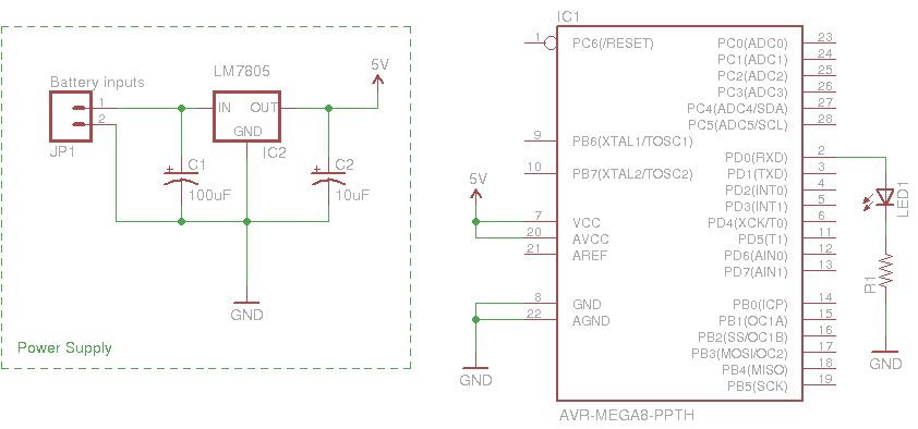
Above is the circuit we are using as an example. The a simple 5v regulator circuit using an LM7805 linear regulator and two filtering capacitors is on the left, separated from the rest by a dotted box. If you already have some type of regulated 5v supply save yourself some time and use that.
You may also notice that the chip in the schematic is labelled AVR-MEGA8. The ATmega168 that we’re using is pin-compatible with at ATmega8. That means that you can swap one for the other and all 28 pins will be where they’re supposed to be, so this will cause no issue.
It is a good practice to add a few components not seen here. There should be two 0.1 uF*capacitors*for decoupling; they filter out fluctuations on the power rails called noise. One between VCC and GND, the other between AVCC and AGND (as close as possible to the pins). There should also be a pull-up resistor on the reset pin with lets an incredibly small amount of current trickle into the pin at a 5V level. This the chip from resetting by accident when it’s floating (not connected so there’s no clear 0 or 5V*value). I’ve omitted these parts for simplicity and it shouldn’t be an issue with this simple project. But as your projects get more complicated, neglecting these considerations will come back to bite you.
The circuit built on a breadboard
I started building the circuit by adding the voltage regulator to the breadboard. Then connect the ground leg to the ground rail on top of your breadboard, and the output leg to the voltage rail of your breadboard. I have also added two wires that I will eventually connect to the positive and negative terminals of a 9V battery.
It is important to read the datasheet for your voltage regulator (example: LM7805) to figure out which lead is input, ground, and output. Your regulator may look different from mine as they do come in different packages. In the image above, the input lead is on the left, the ground is in the middle, and the output lead is to the right.
Now I’ve completed the power supply by adding the 100 uF capacitor between the input leg and ground leg of the regulator, and the 10 uF capacitor between the output leg and ground leg. Pay careful attention to these capacitors, one lead should be marked as negative (a band with a minus sign) on the case of each capacitor. Before adding the microcontroller it would be a good idea to check the voltage output using a multimeter. Too much juice can destroy your new chip.
After checking to make sure I had a steady 5V source, then disconnecting the battery, I added the ATmega168 microcontroller to the board. Note that the dimple is pointing to the left. This is important, as the standard orientation and lead numbering of a DIP package shows that pin 1 is now on the lower left, letting us easily find the other pins that we need.
Power and ground have been connected to the chip as well. Pin 7 (VCC) and Pin 20 (AVCC) have been connected to 5V. Pin 8 (GND) and Pin 22 (AGND) have both been connected to ground.
The final step is to connect the LED to output 0 on Port D. Our schematic tell us that we want to connect the positive lead of the LED to Pin 2 on the ATmega168, and the negative lead should go to an unoccupied row on the breadboard (make sure you don’t attach it to Pin 1). LEDs usually have a small notch flattened on one side of the plastic case to denote the negative leg of the device. The final piece of the puzzle is to connect the negative side of the LED to ground by using our resistor.
In the image above I’ve hooked up a 9V battery , but nothing happened. That’s because there’s no firmware on the chip to make the LED blink yet. We’ll need to fix that in the next step.
Programming our test circuit
Check all of your connections one more time and let’s get ready to program the microcontroller.
Connecting to a programmer
You only need to make six connections in order to program our chip:
- Voltage
- Ground
- Master In Slave Out (MISO)
- Master Out Slave In (MOSI)
- Reset (RST)
- Slave Clock (SCK)
This is true for any programmer that is using In-System Programming. There’s even a standardized 6-pin header that I design into most of my circuits so that you can easily reconnect your programmer to a circuit board and update the firmware down the line. But for this example we’ll just use some jumper wires to make the connections. One thing to keep in the back of your mind is to only use one voltage source when programming. You should either disconnect the power to your circuit while programming, or do not make a connection to the voltage line on your programmer.
Connecting an Arduino as a programmer
Using your Arduino as a programmer is super easy. The first thing you’ll want to do is open up the Arduino IDE, and then open the example software:*ArduinoISP.pde (in the examples/ArduinoISP folder). Flash it to your Arduino in the normal fashion. Now follow the directions for targeting an AVR on a breadboard (bottom of that page). Important: Choose one power source. That is to say, either connect the voltage on the Arduino board to your breadboard, OR connect the battery to the power supply we wired up. Doing both has the potential to damage your hardware.
Here’s how mine looked once I had it hooked up.
Now that everything is ready to go, jump to the next section: Flashing firmware with AVRdude.
Connecting using a DAPA cable
Depending on how you constructed your DAPA cable, it should be pretty easy to make the five connections we need. Notice that the DAPA cable doesn’t have a Voltage connection. The target processor must have its own power source (like the power supply we built on the breadboard) during programming. Here is what my DAPA cable looks like once connected.
If you’re unsure of the connection that need to be made, go back and compare the DAPA cable design to the circuit schematic. Match up our five connections: MISO, MOSI, RST, SCK, and GND.
Flashing firmware with AVRdude
If you did your homework from Part 1 of this series you should already have the cross compiler tools installed. First, download the firmware package (temporarily hosted on Mediafire)*and navigate to that directory in a shell, or at the command prompt. The following commands can be used on Linux and OSX systems to program the chip.
Arduino as the programmer:
avrdude -P usb -b 19200 -c avrisp -p m168 -U flash:w:main.hex DAPA as the programmer:
avrdude -P /dev/parport0 -c dapa -p m168 -U flash:w:main.hex AVR Dragon as the programmer:
avrdude -P usb -c dragon_isp -p m168 -U flash:w:main.hex USBtinyISP as the programmer:
avrdude -P usb -c usbtiny -p m168 -U flash:w:main.hex You can get help from the AVRdude program by running:
avrdude -h That will print out a list of available commands, or you can read the online documentation. Windows users will need to change the /dev/* portion of the command to match your connection. You should find the Windows page of the online manual particularly helpful for this. Standard Windows port names include com0, com1, etc. for serial ports and lpt0, lpt1, etc. for parallel ports.
As for the other flags used in the programming commands above:
When using the Arduino as an ISP programmer you must specify the speed, using ‘-b’. That value is set in the Arduino sketch and should be 19200 by default.
You will always need to specify what kind of chip is connected to the programmer. Here I’ve used ‘-p m168′ for our ATmega168. Get a list of all compatible microprocessors by typing
avrdude -p ? The same is true for specifying a programmer. You can change the ‘-p’ to ‘-c’ in the command above to get a list of programmers.
The final option in the commands we used tells the programmer to write (that’s the ‘w’) the file ‘main.hex’ to flash memory. Part of the command is used for many things, including changing the fuse bits on the chip. I’ll talk about this in Part 3 of the series.
Debugging
Your LED should be flashing away quite happily at this point. What’s that? It’s not? Time to start the real learning. Here’s a list to get you started:
- Did you successfully program the chip? You should get the message: “258 bytes of flash verified” and “avrdude done. Thank you.”
- If you had an error during programming, check first to make sure there is power going to your chip.
- Try the programming command again using ‘-v’ in place of ‘flash:w:main.hex’. This will just attempt to talk to the chip instead of writing to it, and is very handy when working out programming bugs
- Recheck your programming connections to ensure you’ve got the correct signals connected to the right pins
- Make sure you have the correct port on the computer and that you have permission to use that port. Linux users may try talking to the chip with the -v flag as ROOT to discover if there is a permission problem. If this works you need to add your user to the group that has permission to access the port the programmer is connected to
- If you did successfully program the chip you should recheck your hardware. Is the LED installed backwards, preventing it from lighting up?
- Take a trip to Google and start searching… this usually plays a roll in the development process so don’t feel bad. A lot of folks have already experienced the trouble you’re having and they made it through okay in the end.
Conclusion
You’ve done it, your first embedded circuit is alive! For now it will just flash to let you know everything is working. But next time we’ll talk about how this was accomplished, what we can do to make it behave differently, and how to use the compiler to translate our code changes into a file that the microcontroller can run. Thanks for reading and we’ll see you back here for the next installment.
Follow Me
@szczys
Resources
Firmware package: AVRtut_pt2.zip (temporarily hosted on Mediafire)
Atmel AVR ATmega168 Datasheet (PDF)
AVR dude online documentation
AVR In-System Programming Application Note (PDF)
AVR ISP Programming Header:
Filed under: how-to, Microcontrollers


Tags for this Thread
+ Reply to Thread
Results 1 to 1 of 1
Thread: AVR Programming 02: The Hardware
-
10-25-2010, 07:00 PM #1
 Senior Member
Status- Offline
Join Date- Mar 2009
Posts- 32,719
Downloads- 0
Uploads- 0
AVR Programming 02: The Hardware


 Reply
ReplyThread Information
Users Browsing this Thread
There are currently 1 users browsing this thread. (0 members and 1 guests)
Similar Threads
-
Hardware XOR for output pins on AVR microcontrollers
By Diablo in forum Hack the PlanetReplies: 0Last Post: 07-10-2011, 09:43 AM -
Hardware Handshaking for AVR
By Diablo in forum Hack the PlanetReplies: 0Last Post: 05-17-2011, 08:05 PM -
AVR Programming 01: Introduction
By Diablo in forum Hack the PlanetReplies: 0Last Post: 10-23-2010, 07:00 PM -
How hard is to shift from software programming( Java, Perl etc) to Hardware Programming?
By har3000 in forum Discuss PERLReplies: 0Last Post: 03-17-2009, 11:18 PM -
How hard is to shift from software programming( Java, Perl etc) to Hardware Programming?
By har3000 in forum Discuss PERLReplies: 0Last Post: 03-17-2009, 08:39 PM


Bookmarks